Forum
    • Categories
    • Register
    • Login
    1. Home
    2. griffinboy
    3. Posts
    • Profile
    • Following 9
    • Followers 12
    • Topics 125
    • Posts 1,090
    • Groups 1

    Posts

    Recent Best Controversial
    • [BLOG] How does DSP work? [Part 3]

      Part 1
      Part 2

      How does DSP work? [Part 3]

      This time, we're going to look at distortion.

      In Part 1, I briefly described distortion as "bending the waveform" by changing the sample values.
      Now let's unpack what that actually means.

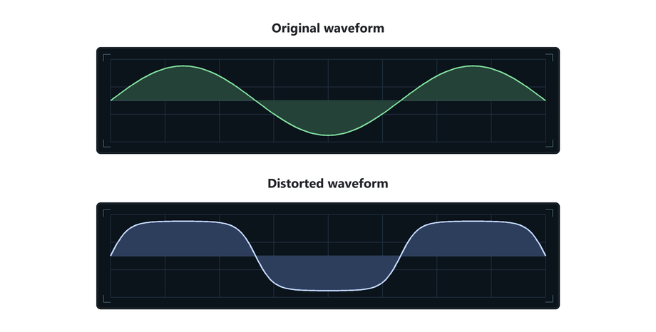
      Distorting a waveform

      To "distort" something means to change its shape.

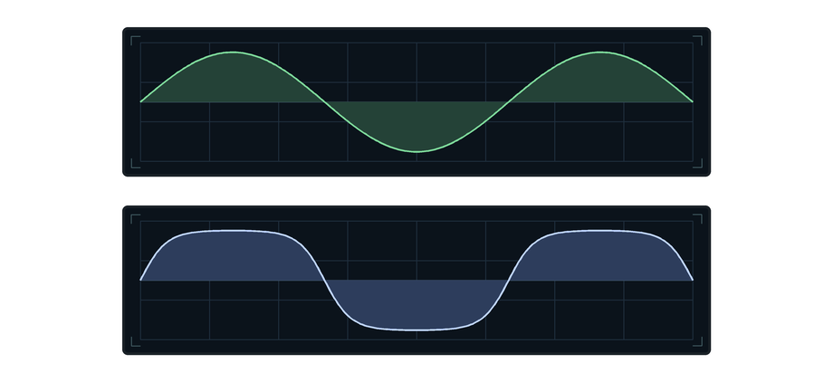
      A distortion effect does exactly that to a waveform:

      88b1a706-e7d2-401e-8b68-854c0c78a4df-distortion-shape.png

      We talked previously about how in a gain/volume effect, every sample is multiplied by the same amount.
      The waveform becomes taller or shorter, but it keeps the same shape.

      A distortion effect changes sample heights by different amounts.
      That is what allows the waveform to bend shape.

      Clipping

      The simplest example of distortion is clipping.

      For example, a clipper that only allows sample values between -1.0 and +1.0.

      (fact: Most audio file formats will clip at this value)

      Values inside that range are left alone.
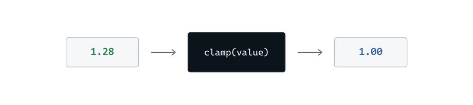
      Anything above +1.0 or below -1.0 is clamped.

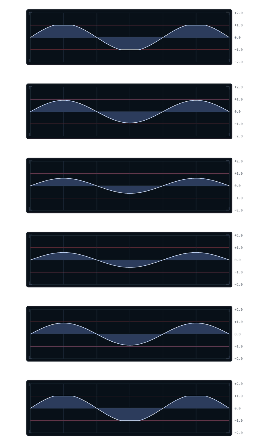
      Watch what happens as the waveform gets louder:

      62a3a3c9-0cde-49d6-b4ff-55b81cf7b7a9-clipping-drive.gif

      At first, the waveform simply gets taller.

      Once the peaks reach the limits, they cannot get any taller.
      That's how a clipper works. This is a distortion.

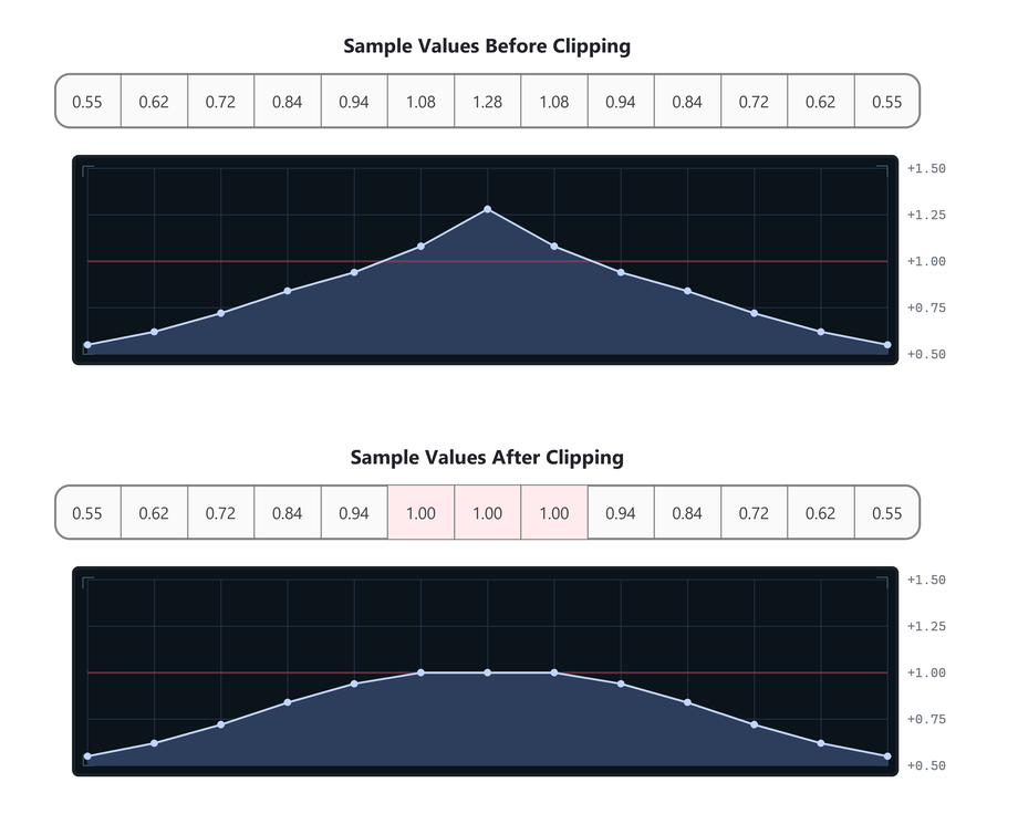
      Let's zoom in and look at a few of the sample values:

      585f2c9d-f85f-433e-bd11-bcb730cc0210-clipping-samples.png

      Only the sample values that exceed the limits are changed.
      The extra height is cut off, leaving the waveform with flat edges.

      In pseudocode, the whole effect could be written like this:

      for each sample in the buffer:
          sample = clamp(sample, -1.0, 1.0)
      

      In other words:
      if the sample value is less than -1.0, it gets set to -1.0.
      if the sample value is greater than 1.0, it gets set to 1.0.

      Waveshaping

      This kind of distortion is called a Waveshaper.
      Hardclipping is just the straightforward clamp.

      9bcd1f2d-c637-45bc-850e-ff1a41ad3482-function-one-value.png

      But we can use other rules/functions to create different waveshapers.

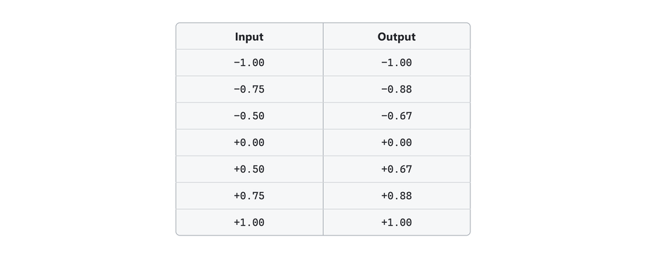
      You can create waveshapers by defining a function that maps input values to output values.

      174ff98f-2991-4840-8d7f-c14e30f8cde7-mapping-pairs.png

      In other words:
      If the original sample value is equal to -0.75 we set it to -0.88.
      If the original sample value is equal to -0.50 we set it to -0.67,
      and so on.

      This is called mapping.
      One value is mapped to another value.

      And the table is called a lookup table.

      Drawing the table

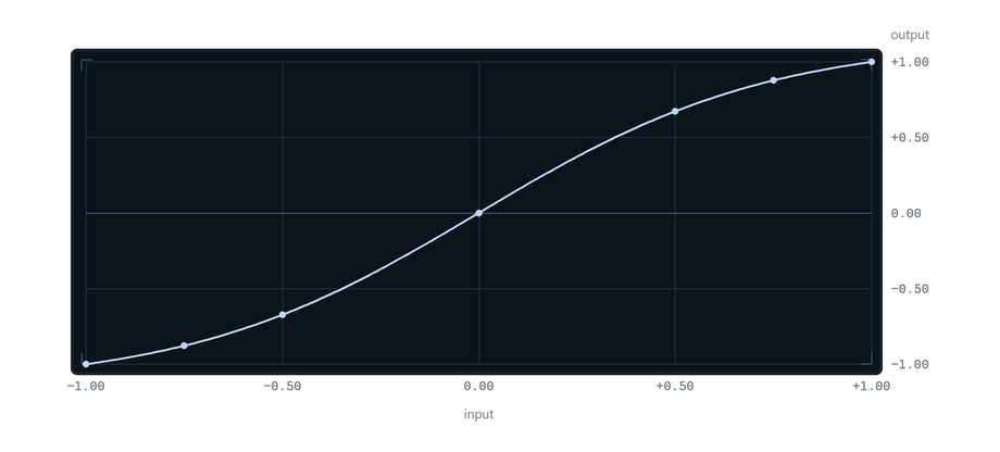
      The input and output mapping can also be drawn as points on a graph.
      You've probably seen this kind of thing before:

      aab8ad25-cb34-43a8-bfd2-3e89c5bef259-mapping-curve.png

      It's an easy way to visualize the waveshaper.

      Input values run along the bottom.
      Output values run up the right side.

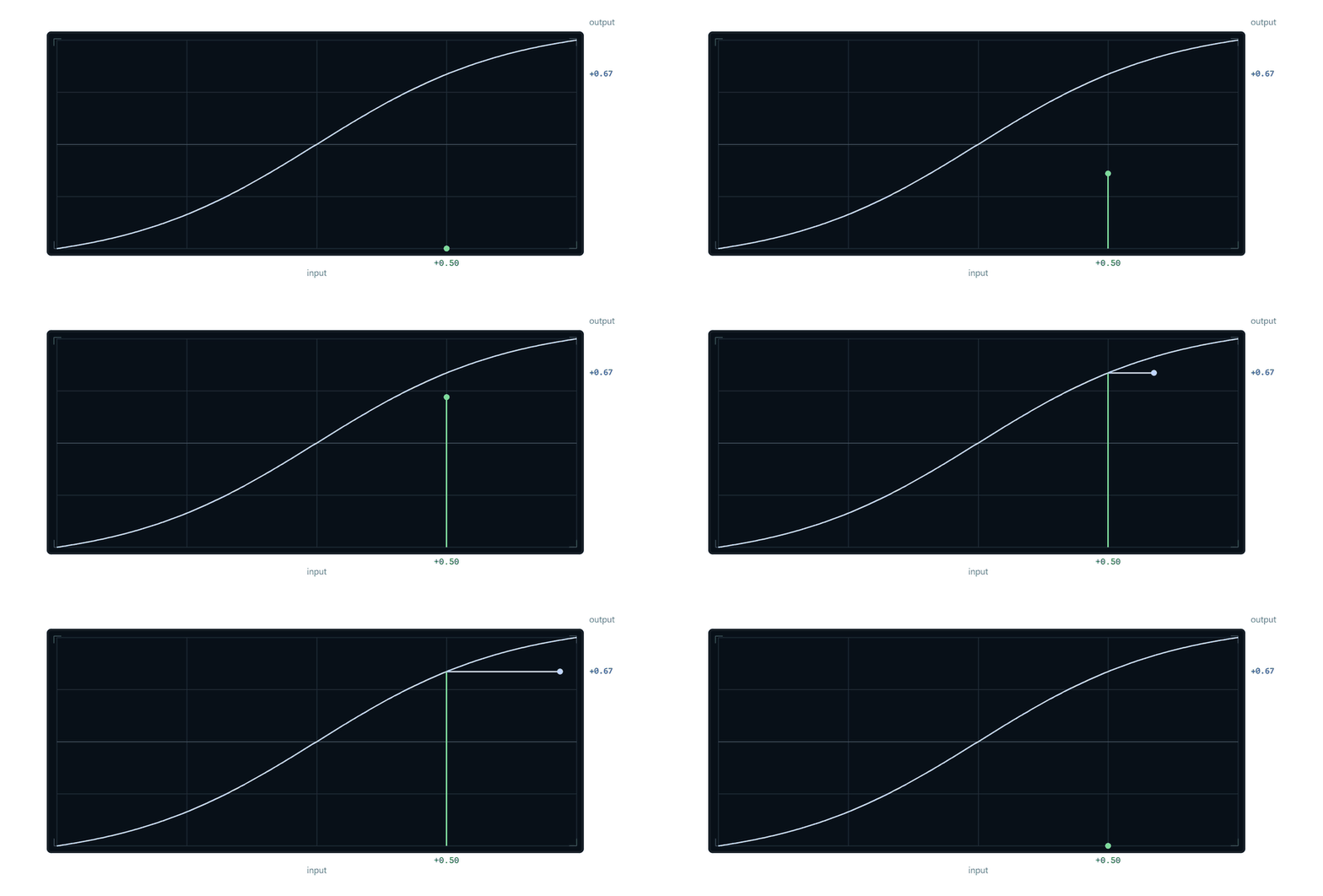
      To look up an input of 0.50, start at 0.50 along the bottom, move up until the line is reached, then move right to read the output:

      db05a93e-37b5-4e34-bf1c-026ffa55ce31-curve-lookup.gif

      The result is 0.67.

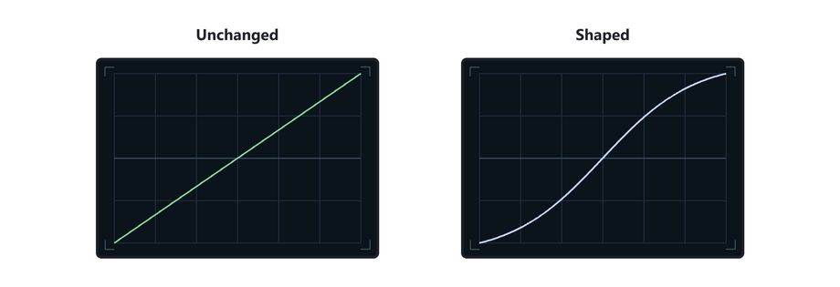
      This plot is called a transfer curve or waveshaper curve.

      bc282e62-4fae-4ad5-b594-ef945a0d6966-identity-and-shaper.png

      Bending the line means we are mapping the samples to different output values.

      A waveshaper

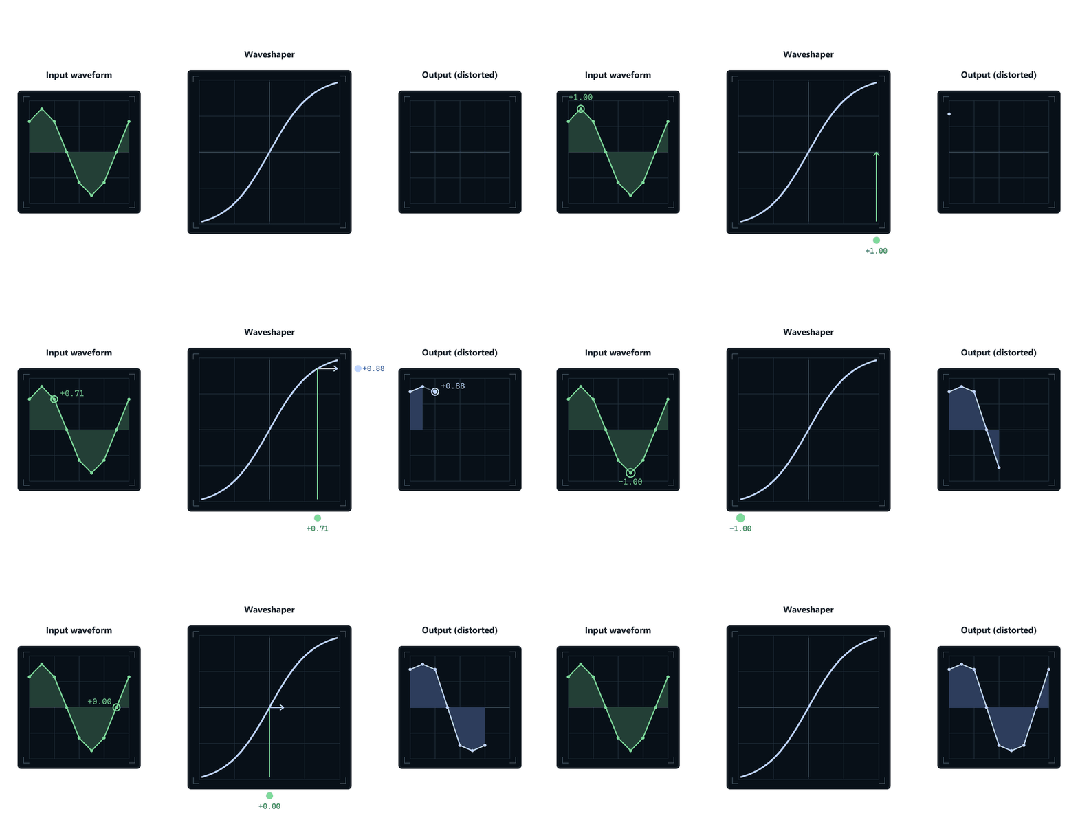
      Here is a waveshaper processing a waveform:

      4fa77841-29c4-448a-bd75-340360a71ff0-waveshaper-samples.gif

      For each sample of the original wave, we look up the input value on the transfer curve,
      and replace it with the corresponding output value.

      The same process on a more dense smooth waveform looks like this:

      89c81430-ee51-4fca-94af-020254731854-waveshaper-waveform.png

      The Math

      The input and output mappings do not have to be stored in a lookup table.
      Some waveshaper distortions use a table, but some use a formula instead.

      Here is the most common "soft-clipping" formula:

      output = tanh(input * drive)
      

      input is the current sample value.
      tanh is a math function that returns the new sample value.

      The function is simply another way of providing an input-to-output map.

      (You could also use sin, cos, or any other function that takes an input value and gives you an output value!)

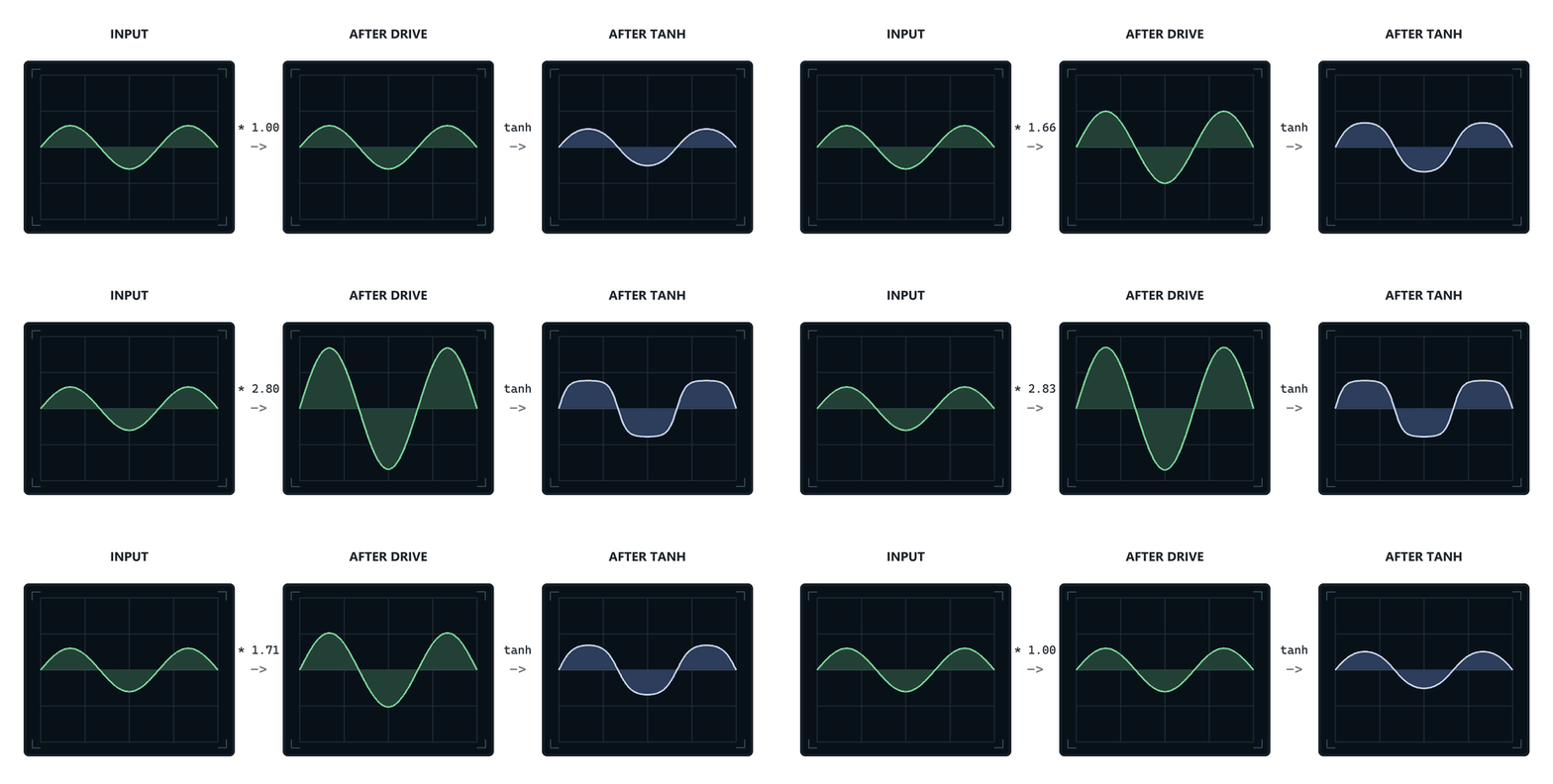
      The drive multiplication in my code makes the original sample value larger (increases gain) before tanh waveshapes the output.
      Tanh has more of a shape at the extreme edges, so increasing the volume of our waveform means we get mapped with all those strong parts of the curve.
      And get a more warped (distorted) waveform.

      bcdc3b56-7673-49dc-aba6-bc153a4f23b7-waveshaper-drive.gif

      Basically we get more distortion when we go into the waveshaper with a louder signal.

      The algorithm is still very simple:

      for each sample in the buffer:
          sample = tanh(sample * drive)
      

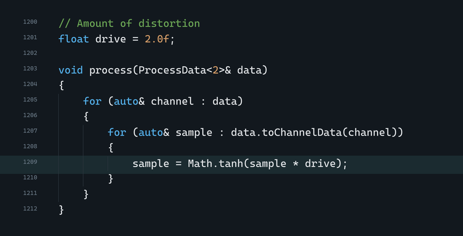
      In HISE-style C++:

      b1aa719a-7b52-4613-abb3-cb385b65a8d1-hise-waveshaper-cpp.png

      HISE's math.expr node does exactly this kind of thing, and it lets you type in your own waveshaping formula!

      85d91bf7-130f-483c-b0d7-a486664dd23f-image.png

      What distortion sounds like

      Different shaped waveforms sound different (well duh).

      A sine wave sounds smooth and pure.
      A square wave sounds harsh and loud.

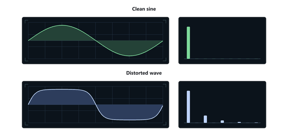
      When we apply waveshaping, we are bending the waveform to make new waveforms.

      37ec97d5-de58-43d0-af8c-a7215c506e4c-distortion-harmonics.png

      More bending changes the shape more (and creates all kinds of harmonics)!

      You can use a lot of different kinds of formulas to bend waveforms in weird ways.
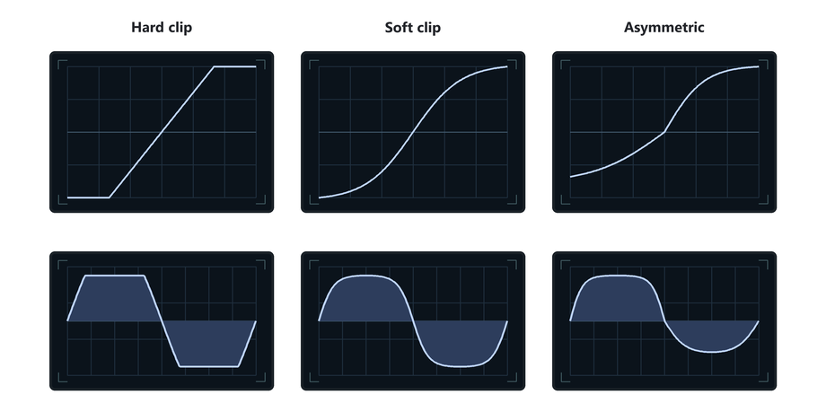
      Different transfer curves create different effects!

      ea20e5d9-6987-4cfe-b677-6fb11a2d830f-distortion-family.png

      To Recap

      A distortion effect changes the shape of a waveform by altering the sample values.

      A clipper does this by limiting/clamping sample values.

      Waveshapers use a function to map each input sample value to a new output value.
      You can visualise this mapping nicely as a transfer curve.

      Apply the mapping to every sample in the buffer, and the new sample heights you get, form a distorted waveform.

      That is how a waveshaper works.

      posted in C++ Development
      griffinboyG
      griffinboy
    • RE: Made a thing: Roland JX-8P/JC-10/MKS-70 emulation in HISE

      @Morphoice

      Great work, it's amazing to see how far you've come in what feels like such a short span of time!
      So cool

      posted in General Questions
      griffinboyG
      griffinboy
    • [BLOG] How does DSP work? [Part 2]

      How does DSP work? [Part 2]

      Welcome back!

      In the previous part, we saw that audio effects work by changing sample values.
      And we saw that a volume effect is just multiplication.

      Next you might be wondering: how does something like a filter work?
      That's the question we are going to answer today.

      We're going to start with the simplest example of a filter: a smoother.

      A smoother is a low pass filter in its simplest form.
      The reason will become clear as we build one.

      Low pass filter

      You probably already know that a low-pass filter removes high frequencies.

      But inside a DSP effect, the audio waveform is just a block of sample values:

      [0.14,  0.21,  0.08,  0.29,  -0.04,  -0.18,  -0.11,  -0.32,  ...]
      

      Those numbers are the waveform.
      So how are we supposed to alter these sample values to remove high frequencies?
      let me explain:


      You probably already know that frequency is how fast a waveform is.
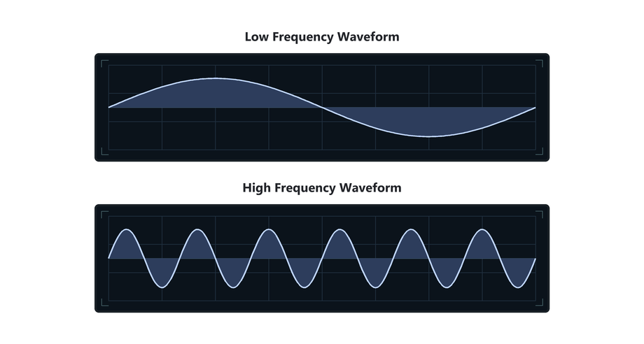
      8900b400-06e0-4b63-942f-936a68c8cbf1-frequency-comparison.png

      And of course, a waveform can contain many frequencies at once.
      For example, if we add two waves together:
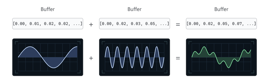
      60fcc656-77ef-4b7b-9e50-79ae592e50f8-frequency-addition.png

      We get a wave that contains high and low frequencies.

      So how do we remove the high frequencies from this kind of wave?

      Let's demonstrate with a complex wave.
      Here is a waveform with plenty of high-frequency content:
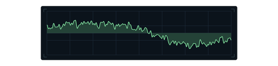
      ac0533dd-f6de-4cfc-855e-f0eda1543b8b-high-frequency-input.png

      The broad sine-like shape is low frequency.
      The fine, noisy-looking details are higher frequencies.

      Now watch what happens when we low-pass the sound:
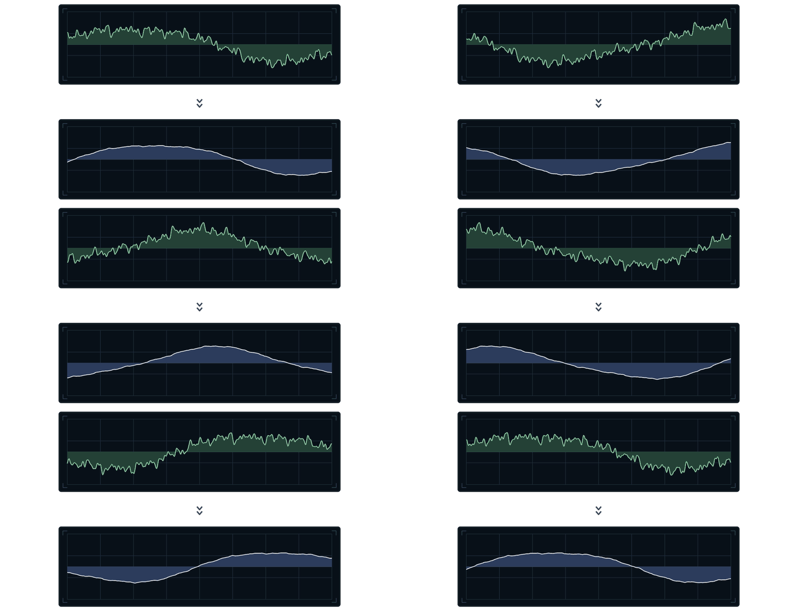
      3133c6e5-070d-44ce-bc48-d498e94b7a77-smoother-audio-stream.gif

      The noisy detail is removed, while the broad low-frequency shape remains.

      The waveform looks smoothed! A smoothing algorithm can remove the high frequencies!

      A Smoother

      So let's look at how a smoother works.

      [My explanation may be a little hard to follow - bear with me please! I will try and explain it in a few different ways]

      There are many ways to write a smoother.
      The version we're going to use generates a new, smoothed waveform in place of the original one.

      The algorithm works like this:
      Every sample, look at the original waveform sample, and move our new waveform sample (the smoothed waveform) towards it.
      But only move it a small amount each sample.

      Here is an animation that shows the algorithm in action:

      34f5e99b-bba3-44c0-9959-e66609a7855c-smoother-homing.gif

      Green is the original waveform sample value.
      Blue is our smoothed waveform we are creating.

      We use the green as a "target", and our smoothed value will move towards it over time.

      Notice how the original (Green) instantly moves to the new sample value, while our smoothed (Blue) value takes a while to catch up.

      Basically, it's incapable of moving fast!
      In other words... it can't be high frequency. Only low frequency!

      Here is the same process running from sample to sample, on a (very zoomed in) waveform:
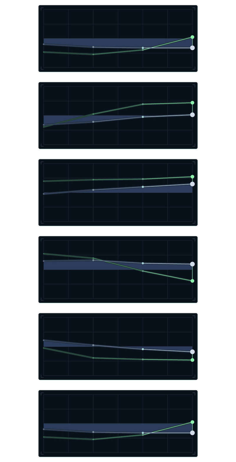
      678ed904-48b5-406b-970d-dcfdf6e74f0f-smoother-sample-by-sample.gif

      At the right edge, green is the current sample of the original waveform, and blue is our smoothed value.

      The smoothing algorithm works by starting from the previous blue value, and then moving towards the green target sample value.

      The resulting smoothed waveform is basically a slow, tired version of the original wave.
      It can follow the broad movements, but it can't keep up with quick details

      The algorithm looks like this:

      var green;
      
      for each sample in the chunk:
          move the green value partway towards the current sample
          output the green value
      

      The Math

      Now let's write the smoothing algorithm as pseudocode:

      amount = 0.1
      smoothedValue = 0.0
      
      for each sample in the chunk:
          smoothedValue = lerp(smoothedValue, sample, amount)
          sample = smoothedValue
      

      smoothedValue is the current height of the blue waveform.
      It starts at 0.0, and it is kept after each sample so that the next calculation can continue from the same height.

      For each sample, lerp moves smoothedValue towards the height of the original waveform.
      The amount controls how far it is allowed to move.

      An amount of 1.0 reaches the original sample value immediately.
      An amount of 0.1 only moves one tenth of the distance.

      lerp is short for a linear interpolation function.
      In this case, it calculates a new sample value (height) between the current smoothedValue and the original sample.

      The calculation inside lerp is:

      smoothedValue += (sample - smoothedValue) * amount
      

      sample - smoothedValue measures the distance between the blue value and the green target.
      Multiplying that distance by amount chooses how much of the distance to travel.
      Adding the result to smoothedValue moves the blue value towards the green one.

      Finally, we output the smoothedValue.

      Because every calculation continues from the value calculated for the previous sample, repeating this process across the waveform for every sample in the buffer, produces exponential smoothing.

      In HISE-Style C++

      The same calculation in C++ looks like this:
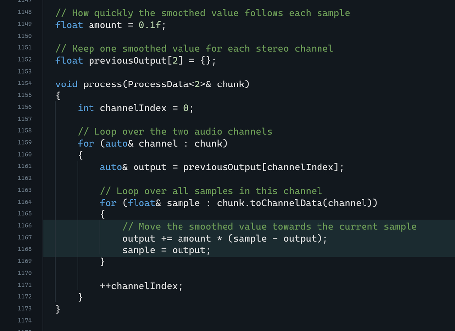
      d73cd8ed-bac2-49f3-b048-37d8fd090538-hise-smoother-cpp.png

      Some trivia:
      That stored value is called the filter's state.
      Because each result depends on the result from the sample before it, this is a recursive filter, also called an IIR filter.
      With one stored value per channel, this particular algorithm is called a one-pole low-pass filter.

      Cutoff Frequency

      Our example code uses a fixed amount of 0.1.

      If we set amount to 1.0, the smoothed value reaches every sample immediately.
      Nothing is smoothed.

      With a smaller amount, the smoothed value takes longer to reach each sample:
      The smoothed value changes more slowly, so more high-frequency detail is flattened.

      When this calculation is used in an audio filter effect, the control is normally presented as a cutoff frequency in Hz.
      This is done using some extra conversion math.
      The cutoff frequency and Daw sample rate are then converted into the amount used by the code.
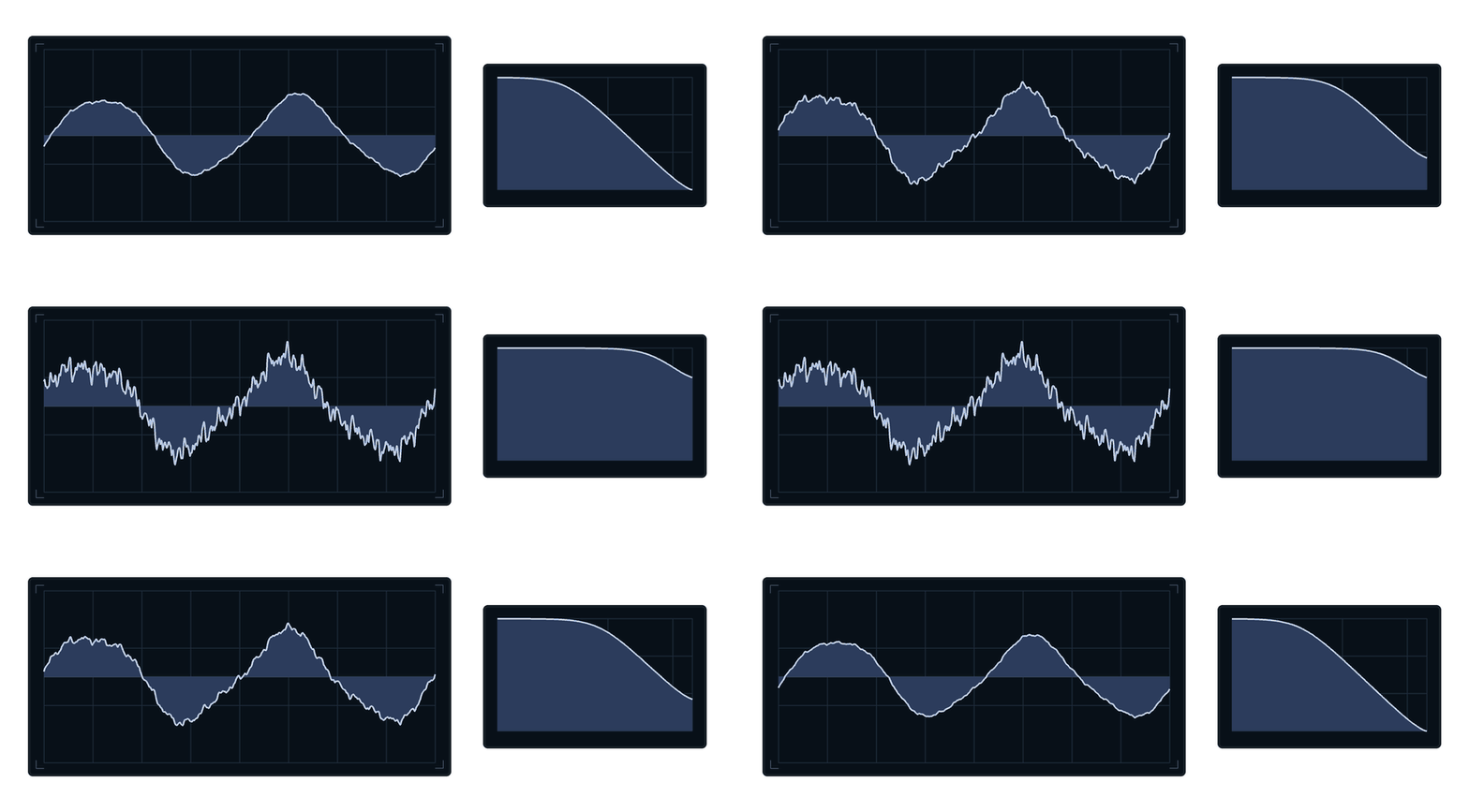
      0a10c413-0615-417a-addf-7e62f0c8db05-smoother-filter-curve.gif

      ^ The smoother with changing amount (cutoff):

      At a low cutoff, the blue waveform loses most of its fine detail.
      As the cutoff rises, the blue waveform follows more of the detail.

      Other Audio Filters

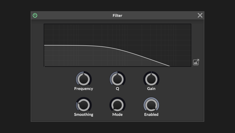
      The smoother I showed you is a real one-pole low-pass filter.
      Its slope is a gentle 6 dB per octave!

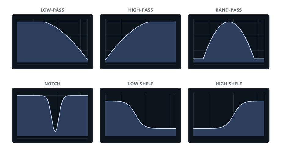
      But audio filters can also have steeper slopes, resonance, and completely different shapes:
      3ea5832f-160a-4b28-8900-2aff4a699c90-hise-filter-node.png

      Different filter calculations produce different frequency responses:
      1d75aa82-d3b5-45c0-ae69-8e10ef6e9b2a-filter-response-family.png

      More advanced filters store more values, and combine them in different ways.

      Two useful names to look for are state-variable filters and biquad filters.
      You can find the algorithms for these online, and they are also implemented in HISE's Filter node.

      HISE provides a state-variable filter node.
      MusicDSP's Chamberlin state-variable filter provides a compact explanation and working algorithms for SVF filters.
      The Audio EQ Cookbook contains the standard equations for many familiar EQ filter shapes.

      To Recap

      Inside a DSP effect, the audio waveform is made up of chunks of sample values.

      For a one-pole smoother, each sample we calculate a new value partway between its previous result and the incoming sample.

      This adds resistance to fast changes, and suppresses the fine detail in the waveform.

      That "fast detail" contains high-frequency content, so the high frequencies become quieter when we do this.

      posted in C++ Development
      griffinboyG
      griffinboy
    • RE: [BLOG] How does DSP work? [Part 1]

      @David-Healey
      Thank you!
      Maybe with some refinement :)

      It's far from perfect.

      This explanation is just my own attempt to boil down the theory into a simple form.
      ...and it still ended up a bit of a ramble!

      I think it's quite a tricky subject to teach, because in real life there are so many implications and exceptions to every rule.
      Even simple DSP can look a bit monstrous when you layer ontop all of the common optimizations and C++ tricks.

      posted in C++ Development
      griffinboyG
      griffinboy
    • [BLOG] How does DSP work? [Part 1]

      Welcome to the first part of my new blog series!

      To be clear, this is not a series about how to write DSP code in HISE (That tutorial series is coming later).
      Rather, this is a beginner focused, theory-heavy guide on "How does DSP work".

      Understanding this theory, will make it much easier to write your own DSP later.
      So without further ado, let's begin the first part!

      How does DSP work? [Part 1]

      Audio programming does not look like audio.

      c5313d73-44fb-4b88-9622-2f597f65f9ee-dsp-math-sketch.png

      It looks like values and numbers.

      And that's exactly what makes DSP possible.
      Once sound is represented by numbers, code can manipulate it!

      Without further ado, let me explain how audio gets represented as data, and how changing that data changes what you hear.

      Audio as Data

      A speaker makes sound by moving.

      400e18a1-9d5c-4313-bfe2-03ea50b775fe-speaker-waveform.gif

      The line at the top is a waveform.

      For now, think of it as the shape the speaker is following.

      When the waveform moves up, the cone moves one way.
      When the waveform moves down, the cone moves the other way.

      That movement pushes air, and we hear it as sound.


      Real audio is generally faster and messier, but the idea does not change:
      a speaker is following a changing value over time.

      So, if we want to create a sound,
      we need to create a waveform.

      The waveform as numbers

      In digital audio, a waveform is stored as numbers.
      A tiny piece of a waveform might look like this:

      [0.00,  0.70,  0.82,  0.27,  -0.51,  -0.86,  -0.51,  0.27]
      

      So, what is this?

      Well, digital audio does not store a "picture" of a waveform.
      It stores the height over time.

      Plot those heights from left to right, and the waveform appears.

      1e87fe4d-41b8-4f27-a13b-4c8f12a555f8-sample-array-to-plot.png

      These height numbers are called samples.
      Because each number is one tiny "sample" of the waveform height at one moment in time.

      The order matters because the order is time:

      73a0dd64-1d05-42a1-9db1-893ecfa99eec-sample-table-playback.gif

      The array of data is the digital waveform. The drawing is the same data made easier to see.

      Lots of samples

      The example I showed you above, is tiny on purpose.
      Real audio has far more samples than this.

      I'm sure you've heard of "Sample rate".

      44.1k, 48k. 96k, etc.
      With 48k being a common DAW sample rate.

      Well, running a program at 48 kHz means that one second of mono audio contains 48,000 sample values.

      That's the kind of high resolution that produces smooth waves.
      The simple drawings in this article are just a readable version.
      But real audio is the same thing packed more tightly in time.

      5719a9b4-2c59-4ce5-ab1a-b71224c0bb95-dense-sample-waveform.png

      (^ That's just something to be aware of. You don't have to worry about it for now, since I'll be continuing to use small pieces of audio for the sake of this article).


      So far we have looked at audio as one long strip of sample values.
      But we have not talked about how a plugin generates this big stream of audio.

      So let's talk about chunks / buffers.

      Chunks (Buffers)

      Real time DSP does not work on a big, long, sound in one go.
      - It processes chunks of audio.

      9c4096e2-3694-4ded-9d60-66cffae5cc0f-waveform-buffer-split.png

      A DSP effect takes a short chunk of audio, processes it, then moves on to the next chunk.

      An effect is like this:

      A chunk comes in.
      The effect changes the numbers inside it.
      The chunk goes out.
      Then the next chunk comes in.

      This is the basic shape of a normal audio effect.

      da8e66ea-dfc9-4e57-a281-63b38c6b8106-buffer-through-dsp.gif

      (The reason we process in small chunks of sound is efficiency related. But it's also practical:
      It's quite useful to have access to a whole portion of audio at a time)

      A simple example: volume

      Let's look at a real-life example.
      Volume is a good example because it's easy to see.

      cfe8b407-2b25-4c75-82df-5d5077c169cc-hise-gain-node.png

      You probably already know:
      Volume is the height of the waveform.

      Making a waveform less tall means the speaker isn't moving as much.
      In other words, height affects volume.

      de975f42-89a3-4f64-877b-554074d41d3c-waveform-volume-scale.gif

      ...And earlier we saw that we store waveforms as height values.

      (you can see where I'm going with this).

      If we want to make the waveform quieter,
      all we need to do is make the sample values smaller.

      For example if we multiply every sample by 0.5 (half):

      The shape is the same.
      The height is half as large.

      9388e6dc-9e8b-4ee8-9422-5066a1096341-sample-gain-comparison.png

      We've made the waveform half as loud.

      The algorithm for a volume effect then boils down to:

      f837f20d-a86c-4c31-a30c-97ae75417488-hise-gain-node-code.png

      In pseudocode form:

      receive buffer
      
      for each sample in the buffer
      {
          sample = sample * gain;
      }
      
      ^ do the above for every buffer we receive
      

      So:

      If gain is 1.0, the sample values stay the same.
      If gain is 0.5, the waveform is half as tall.
      If gain is 2.0, the waveform is twice as loud/tall.
      If gain is 0.0, every sample becomes zero, which is silence.

      In actual C++ DSP:

      0ab2a9dd-9b10-4a29-b1ee-36186842477b-hise-gain-node-cpp-code.png

      (^ I bet you understand this now!)

      The main part of the effect is a function that receives a buffer of samples (a chunk) and processes them using math.
      That's what DSP code looks like!

      The real HISE gain node has some extra controls and parameter smoothing, but the core audio operation is still this simple multiplication.

      The Lesson

      Honestly that's pretty much it.
      DSP is not very complicated.

      Most Audio effects work by:

      Take a buffer of sample values,
      change those values,
      and pass the buffer onward

      A Gain effect multiplies the samples.
      
      A Distortion bends the waveform shape by changing the samples.
      
      A Delay stores samples and plays them back later.
      

      Oscillators are a slightly different case. They create new sample values rather than affecting incoming ones.

      0409a709-0ce4-4805-84c9-c680373dfdf4-oscillator-block-factory.gif

      ^ And I'm if being 100% honest, this isn't quite the whole picture.

      If we zoom out a little, you'll see that there is actually a bigger loop going on.
      Where something is sending us a buffer, and asking our DSP to process or fill it.
      Then it takes that buffer back and sends it to the next place.

      (in our case, that "something" is HISE / JUCE).

      f79a05e7-920f-44c5-96e3-bcb2cc2b72f7-plugin-chain-routing.gif

      For an effect, something is going to send us a chunk and say "please process this" and we do that.

      For an oscillator, we might be given an empty chunk and we just need to write a waveform into the chunk and send that back.

      To Recap

      1. The table, the waveform, the buffer.
      They are different visualizations of the same thing:
      sample values over time.

      9ae6b3ad-0c76-440b-9247-d89d85dac4cf-recap-signal-views.png

      2. Audio plugins work by processing chunks of samples. These chunks are passed around between different oscillators and effects.

      f79a05e7-920f-44c5-96e3-bcb2cc2b72f7-plugin-chain-routing.gif

      3. Down the line, part of the program will mix the chunks and send them to the speaker and we will hear the waveform (we don't usually have to worry about that part, Hise or Juce will take care of those parts for us).

      a62c0ed0-1d53-4476-89d3-bc2628f0ba84-output-stream-to-speaker.gif

      Next: filters and other effects

      I know what you're thinking:
      Gain makes sense, but how do we create filters and other kinds of effects? What kind of maths causes those?

      Look forward to [Part 2].

      posted in C++ Development
      griffinboyG
      griffinboy
    • RE: Hi! πŸ‘‹πŸ»πŸ™ŒπŸ»

      @gonzalo
      Great to have you here!

      posted in Blog Entries
      griffinboyG
      griffinboy
    • RE: Which modulation routing method would you recommend for my project?

      @David-Healey Really? He's talking about block and frame sizes though? DSP usually reads parameter values at the start of each block. Using larger blocks means you might not be reading the parameters / LFO modulation as frequently. (assuming the modulation / parameter callbacks are also being called fast enough by the modulator)

      posted in General Questions
      griffinboyG
      griffinboy
    • RE: Which modulation routing method would you recommend for my project?

      @David-Healey

      He means the rate at which the LFO actually updates the DSP it's connected to, I assume.

      This does vary in HISE and affects the sound of High Rate modulation.
      I haven't measured every path myself so I cannot give a breakdown here.

      But it's definately possible to do a sweep with a good AI agent, or use the REST system to probe all the Hise processing paths and get the exact numbers for all the different scenarios.

      I started to do this myself, but I haven't covered all of them and I'm using lots of custom nodes, where HISE allows you to set the rate of modulation yourself and so this isn't so unknown.

      What I do know is that HISE doesn't seem to go faster than updating DSP every 8 samples.
      I might be wrong on that point but that's what I've observed for C++ nodes anyhow. Maybe it's different for native DSP.

      posted in General Questions
      griffinboyG
      griffinboy
    • RE: VST/plugin GUI design + launch graphics β€” ads, motion, web

      @lalalandsynth

      Love the knobs!

      posted in General Questions
      griffinboyG
      griffinboy
    • RE: Cannot access HISE Store

      @alobassmann

      I believe the store is going to be launched with the release of HISE 5

      posted in Bug Reports
      griffinboyG
      griffinboy
    • RE: [Research Paper] An Efficient Simulation of the EMS VCS3 Filter *updated with audio comparison examples

      @griffinboy

      I realized that these plots are a little misleading.

      The VCS3 filter is highly nonlinear and "bubbles" and so taking a measurement of frequency response is quite difficult since the filter is moving around on it's own accord all the time...!

      Here is a more detailed FFT that shows how the filters do match more closely than the graphics in my paper would suggest.

      .

      Black is the slow accurate VCS3, Red is my optimized VCS3.
      Not oversampled.

      c4000_fb9_m42__one3_c050_k2.png
      c10000_fb9_m42__one3_c050_k2.png
      c2000_fb6_m42__one3_c050_k2.png
      c10000_fb9_m42__one3_c050_k2.png

      When oversampled, I found the proposed model to be perceptually close to the slower accurate model. The resonance and cutoff and gain values differ slightly, but the important aspects of the filter are retained.

      posted in C++ Development
      griffinboyG
      griffinboy
    • RE: [Research Paper] An Efficient Simulation of the EMS VCS3 Filter *updated with audio comparison examples

      @griffinboy

      PDF version.

      ems_vcs3_reduced_diode_ladder_paper.pdf

      posted in C++ Development
      griffinboyG
      griffinboy
    • RE: [Research Paper] An Efficient Simulation of the EMS VCS3 Filter *updated with audio comparison examples

      @griffinboy

      ems_vcs3_reduced_diode_ladder_page_09.png
      ems_vcs3_reduced_diode_ladder_page_10.png
      ems_vcs3_reduced_diode_ladder_page_11.png

      posted in C++ Development
      griffinboyG
      griffinboy
    • [Research Paper] An Efficient Simulation of the EMS VCS3 Filter *updated with audio comparison examples

      I've been wanting to share some of my R&D for a while -
      I'm constantly creating new DSP on commission, but I'm always short on time to talk about it because I am buried under work (the aforementioned R&D).

      At some point I had the realisation that maybe one of these newer AI agentic models could look at my code and scribbles, and mock up something vaguely paper-shaped from it.

      I then edited it by hand to add more details, and check correctness.

      The result surprisingly wasn't too bad and I've checked that all the math and facts are correct.
      So I'm sharing it here for those who are scientifically inclined, or just interested in the implementation side of this kind of DSP work.

      At a later date I'll rewrite the paper by hand and post a cleaner version.


      Audio comparison companion.

      https://youtu.be/DFSnDCQUov8


      ems_vcs3_reduced_diode_ladder_page_01.png
      ems_vcs3_reduced_diode_ladder_page_02.png
      ems_vcs3_reduced_diode_ladder_page_03.png
      ems_vcs3_reduced_diode_ladder_page_04.png
      ems_vcs3_reduced_diode_ladder_page_05.png
      ems_vcs3_reduced_diode_ladder_page_06.png
      ems_vcs3_reduced_diode_ladder_page_07.png
      ems_vcs3_reduced_diode_ladder_page_08.png

      (continues in comments)

      posted in C++ Development
      griffinboyG
      griffinboy
    • [Bug] Enabling NUM_HARDCODED_FX_MODS breaks custom C++ nodes.

      Hardcoded Master FX parameter modslots can force c++ Third-party node parameters to max

      *I used ChatGPT to help format this bug report so that it's written clearly and thoroughly.
      I apologize for the "Ai aesthetic" residue that leaves behind.

      Branch: I'm on the latest HISE develop branch, pulled and compiled today
      OS: Windows 11
      Juce: I'm using Juce 6 (version: 6.1.3)
      Project flags:

      NUM_HARDCODED_FX_MODS=8
      NUM_HARDCODED_POLY_FX_MODS=8
      

      Summary

      I think there is a bug in the hardcoded Master FX "parameter-modslot" path.
      I didn't want to post a report until I was sure it wasn't my own mistake, but I've been reading the Hise source all day and testing different C+ nodes and in the end I concluded this might be a bug:

      If a third-party node exposes a parameter modslot with ConnectionMode::Parameter , loading that node into a hardcoded Master FX forces the modslot parameter values to get set to the top of their ranges (and stuck there).

      This is not a small issue. For DSP nodes it completely breaks effects, and means you can't use any c++ nodes that have modslots inside monophonic hardcoded master FX.

      I like almost all of my c++ nodes to have modslots so that they can work easily with hise modulation and the matrix modulator. This bug means I have to make modslot and non-modslot versions of every effect, so that I can load the modslot version into poly contexts and the non-modslot one into mono contexts. And then for the mono nodes I have to use a different modulation scheme. Messy.
      (unless I'm misunderstanding something).

      How I found it

      I was testing a compiled third-party DSP node.

      The same node behaved normally in a ScriptFX context, but in a hardcoded Master FX it produced broken / glitchy / extremely wrong output.

      When I removed these project flags and rebuilt, the hardcoded Master FX version started behaving normally again:

      NUM_HARDCODED_FX_MODS=8
      NUM_HARDCODED_POLY_FX_MODS=8
      

      So the issue appears to be tied to hardcoded FX modslots.

      Disabling those flags is not a usable workaround for me, because then hardcoded modslots would be unavailable project-wide.

      Minimal test

      I made four tiny diagnostic third-party nodes.

      Each node has one parameter:

      Parameter_name: ProbeValue
      
      Range:   0.0 to 1.0
      Default: 0.25
      

      Each node outputs a tone whose gain follows ProbeValue.

      Expected result: quiet tone.
      Bug result if the parameter is forced to max: much louder tone.

      Each node exposes the same parameter slot:

      modulation::ConnectionInfo slot;
      slot.connectedParameterIndex = ProbeValueParameter;
      slot.connectionMode = modulation::ConnectionMode::Parameter;
      slot.modulationMode = modulation::ParameterMode::ScaleAdd;
      

      I tested four variants:

      Griffin_ModSlotProbe_NoHandle
      Griffin_ModSlotProbe_WithHandle
      Griffin_ModSlotProbe_FrameHandle
      Griffin_ModSlotProbe_ModNodeHandle
      

      These check whether adding the following details would fix or change the behavior:

      • no handleModulation() function defined
      • handleModulation(double&) { return 0; }
      • block processing forwarded through processFrame() from process()
      • isModNode() == true (yeah, I know that's not going to do anything)

      Result

      In hardcoded Master FX:

      NoHandle       left loud, right silent
      WithHandle     left loud, right silent
      FrameHandle    left loud, right silent
      ModNodeHandle  left loud, right silent
      

      The left channel becoming loud proves ProbeValue was driven from 0.25 to 1.0.
      And the right channel staying silent means handleModulation(double&) callback was not called.

      Expected behaviour

      Ideally, a hardcoded Master FX parameter modslot should not push a node parameter to its maximum value simply because the slot exists.

      If no meaningful modulation value is active, the parameter should keep its current/default value, or the slot should not be treated as connected until there is an actual usable modulation connection.

      Current behaviour

      Currently, with hardcoded FX modslots enabled, a third-party C++ node exposing ConnectionMode::Parameter can get seemingly spammed with max-range parameter values during rendering / stuck at max value (moving the parameter doesn't unstick us, the parameters are stuck to max).

      Why this matters

      I'm assuming that HISE nodes are intended to be modular.
      If that's true, then a node that is poly-capable, or a node that exposes modslots, should be able to function in a mono hardcoded Master FX context too.

      This is also inconvenient for my shipped products. A HISE user can load one of my nodes into HISE and get broken DSP because the hardcoded Master FX modulation path corrupts parameter values.

      The result of all this is that ConnectionMode::Parameter becomes unsafe for third-party hardcoded Master FX products.

      Suspected source bug

      The Hise algorithm seems to do something like this:

      HardcodedMasterFX::applyEffect()
        -> extraMods.processChunkedWithModulation(rd)
        -> ExtraModulatorRuntimeTargetSource::handleModulation(...)
        -> ModChainWithBuffer::getOneModulationValue(startSample)
        -> rd.handleModulation(pIndex, mv)
        -> parameter range convertFrom0to1(mv)
        -> p->callback.call(value)
      

      The important part is in the hardcoded Master FX context, with no active voice state, getOneModulationValue() can return an inactive/default modulation value of 1.0f.

      That normalized 1.0 is then converted through the parameter range, so the node receives the parameter maximum.

      Request

      Could the hardcoded Master FX parameter-modslot path be changed so inactive / unconnected / not-yet-valid modulation does not force parameter-mode slots to max?


      post script: a similar / related bug exists in the Hise synth group, I will write a report on that after a bit more investigation.


      Christoph, Thanks for all your hard work🫑

      posted in Bug Reports
      griffinboyG
      griffinboy
    • RE: VST/plugin GUI design + launch graphics β€” ads, motion, web

      @lalalandsynth

      Ah that makes sense,
      yes indeed that was the only thing.

      In that case, great work all round.
      I'll keep you in mind for some upcoming projects.

      posted in General Questions
      griffinboyG
      griffinboy
    • RE: VST/plugin GUI design + launch graphics β€” ads, motion, web

      @lalalandsynth

      The AI textures aren't my favorite.
      But the majority of the image looks great.
      I like the knobs a lot, and the VU meter is quite elegant!

      posted in General Questions
      griffinboyG
      griffinboy
    • RE: [Devlog] Blog

      @resonant
      Ah! So, you might have heard tell of an upcoming Hise Asset store?
      I don't know the exact plans, but it might be released with the next major Hise version.

      I'm hoping to release a giant bulk of DSP on that platform when it launches, all vetted by Christoph beforehand.
      I've been holding off on releasing any DSP nodes on the forum, in the hope that the store could become an official home for all of them.

      I've made a lot of products in advance:

      Snag_ebec270.png
      (195 Dsp files in my "approved" folder)

      Including some free stuff that I've made for the HISE community.

      I don't currently have an existing storepage for my work, but I do take commissions and licence out my DSP on a per-person basis, so if there is anything in particular you are looking for, feel free to send me a direct message!

      posted in C++ Development
      griffinboyG
      griffinboy
    • [Devlog] Blog

      It has been a while since I've posted any tutorial content.

      I had a brief moment where I released (a single?) guide for making c++ nodes in HISE.
      Some of you probably gave up hope that I'd make another tutorial on the topic.
      But I had always intended to do a full deep dive into C++ DSP, and I've been biding my time waiting for the opportune moment where I would have enough free time to make the content.

      Well, the time is upon us, and I'm finally making the content - in the form of HISE blogs.

      I'm still in the process of designing the blog posts,
      but once I've built enough graphics and animations, I should be able to pump out regular posts that explore different areas of audio coding and science.

      The posts will likely start out quite simple,
      but I plan to dive into some of the advanced modern topics as well, not limited to: neural effects, analog circuit simulation that nulls against hardware, and other topics that I've been writing research papers about.

      Looking forward to discussing with you all soon!

      [work in progress, HISE blogpost development]

      2026-07-01_00-53-59.gif

      [project: analog filter model, new simulation method]

      d99c99e7-a72b-42b9-b320-3bf4d61a5aed-image.png

      Yes... this is a blog post about devloping a blog post.

      posted in C++ Development
      griffinboyG
      griffinboy